<b><font size="3">&#8505; </font></b> Davis weather stations

Davis weather stations

1.1 Davis Vantage Pro and Vantage Vue weather stations

Davis and the market
Davis is a (semi) professional segment weather station. Within this segment, Davis delivers an unbeatable price / quality ratio, which means that within this segment there is hardly any kind of serious competition for Davis.

Davis is the choice for you as a weather enthusiast and the professional who values reliability and accuracy. Davis does not stand still in terms of development. Constant improvements are being made on existing models such as a more accurate VP2 sensor, an improved rain cone, etc.

With the Enviromonitor system, Davis shows that it is also developing innovative new systems. The Enviromonitor system is primarily intended for the business market.

Vantage Pro 2 developments

2000 - Birth Davis Vantage Pro1
2003 - VP1 revision. T / H sensor now separate from ISS board
2005 - Introduction Vantage Pro2 (analogue T / H sensor - 7346.029)
2006 - Jan 1 and beyond: T / H sensor digital
2011 - 1-Aug. Introduction "green dot" data loggers. Dataloggers from before this date do not work with the newer stations.
2013 - From Feb: new model (6410) anemometer, narrow neck. Replace switch with solid state sensor (electronic switch). Magnet now in (replaceable) windspeed cartridge instead of in wind cups.
2014 - Improved rain cone with finger "grips", bird spikes and new dirt filter.
2016 - 1-Jan and beyond (mfg codeASxxx and higher): T / H sensor accuracy 0.3 ° C - 7346.070
2017 - Jan 1 and beyond Aerocone rain cone. Aerodynamically shaped rain cone with dirt filter lock.

Analog VP2 (2004-2005) sensor vs new digital sensors.
The first Vantage Pro2 had an analog sensor (mfg code starting with A4 and A5). Later stations have a digital Thermo / hygro sensor.
A Vantage Pro2 with analog sensor can be upgraded for use with the new digital sensors. For this, the transmitter board must be replaced by a recent version suitable for use with digital sensors.

VP1 and VP2 interchangeable?
No - Console and ISS between VP1 (6310) and VP2 (6312) are not interchangeable.
No - Temp / hum sensors - see item: "Vantage Pro models from 2000"
Yes - Rain meter; anemometer; UV; Solar; Soil moisture; (Soil) temp; Leaf wetness
Yes - 6510xx, 6555 data loggers for consoles produced before 2012.

Note: The US and NON-US (OV - Over Seas) console / ISS parts are not interchangeable due to different transmission frequencies.

Determine the age of your station?
  • Decode first 6 digits of Mfg (bar) code on the back of the console to: YYMMDD.
  • I.e: Mfg code: AA111012P002> First 6 digits: 111012> years:(20)11; month:10 day:12. Console has been produced 12-10-2011
1.2 Models
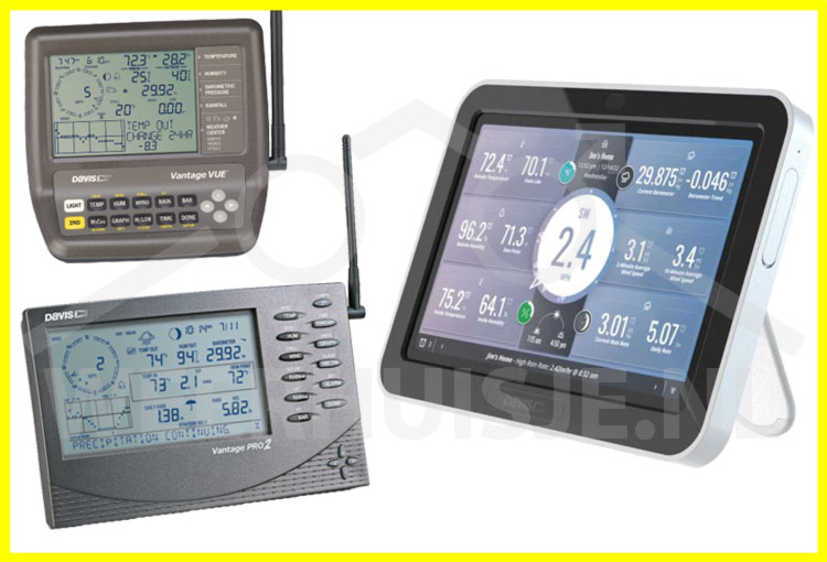
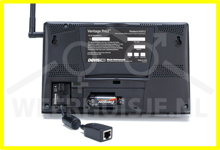
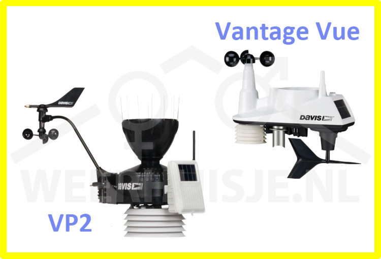
The basis for the Davis weather stations is the Davis Vantage Pro2. This weather station is available in different (more or less extensive) versions. You can also choose the entry model Davis Vantage Vue.

The Vantage Vue uses the same technology as the Vantage Pro2 series and has the standard weather variables. The Vantage Pro2 and Vantage Vue are fully compatible with each other. A Vantage Vue display can therefore easily receive a Vantage Pro2 outdoor unit and vice versa.

Technique
  • The stations operate at 868MHz (EU) frequency.
  • For transmission of the weather data  "frequency hopping" technique is used. This means that all of the  available bandwidth is used to broadcast weather data so disruptions are kept to a minimum.
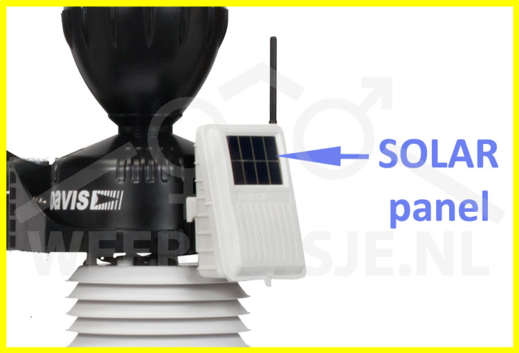
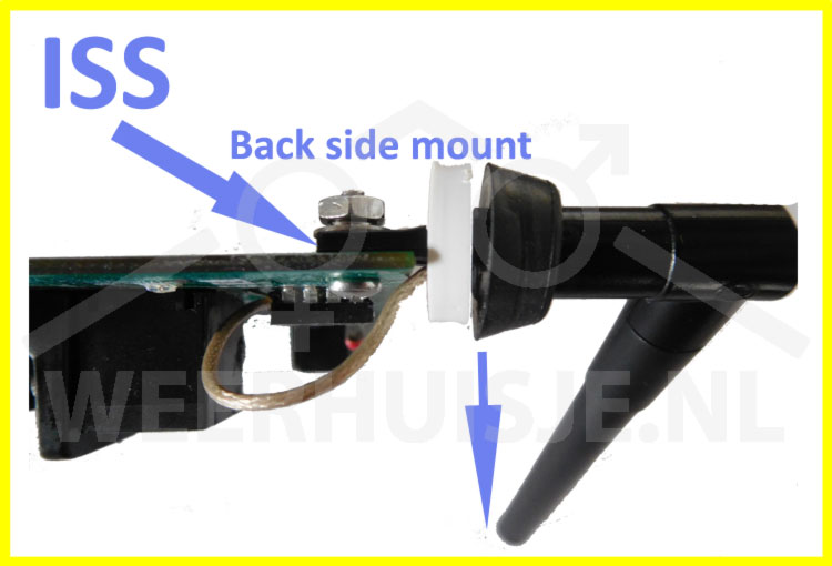
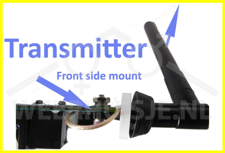
  • The outdoor unit (ISS) transmits weather data every 2,5sec. o the recipient.
  • Recipients do not need to be linked manually. You do not have to worry about it. The receiver automatically scans the available stations.
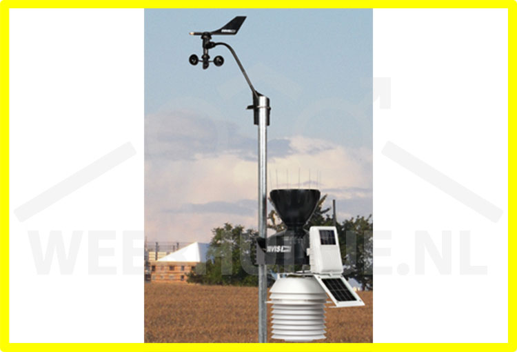
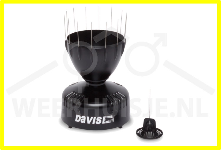
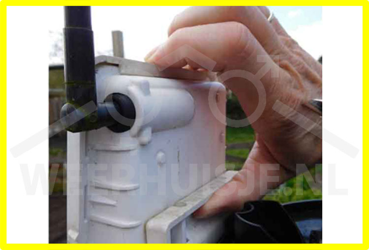
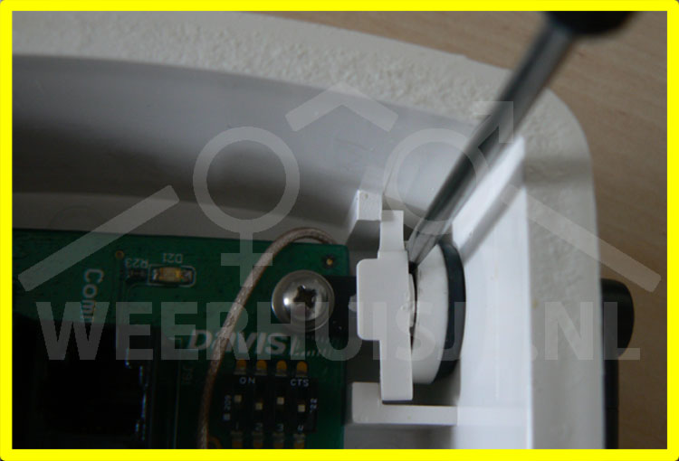
  • The high quality materials used for the outdoor unit are weather and UV resistant.
  • A lot of attention is also paid to the protection of the electronics against the effects of the weather.

Comparison

Comparison Davis stations
VgeVue
Vantage Pro2
Vantage Pro2 +
Station model
6250
VP2Vue
6152C
VueVP2
6152
6153
6162C
6162
6163
Outdoor unit wireless
Extra wireless options possible
*
*
*
Fan ,UV, solar sensor optionally
Incl. 24Hr temp. fan
Incl. UV and solarsensor
* Extra wireless options:
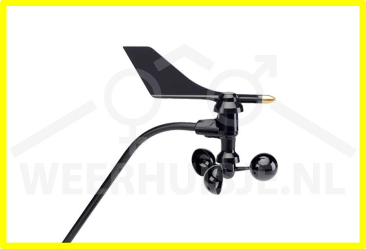
Possibility to connect wireless wind gauge set (6332 + 6410).

1.3 Console
Both the Davis Vantage Pro2 and the Vantage Vue feature an extensive console with internal memory for storage of weather data. Every 2.5 seconds weather data is refreshed resulting in practically real time weather data.

You do have a view of the current situation at any time, especially for stormy situations and downpours. This way you are constantly on top of the weather! Furthermore, the console has a graph with last 24 hours data  for all weather variables.

In addition, the highest / lowest values ​​per day, month and year are displayed at the touch of a button. You will also receive notifications about phenomena such as annual meteorites, the transition to the summer, battery status, etc.

The internal display memory remembers all weather variables during the last 25 hours, 25 days, 25 months, and even 25 years of historic data of rain measurements. This data is also retained after a power failure (as well as all settings do).

The historical data is shown in a graph. You can easily view all individual values ​​with corresponding times. The console furthermore accommodates the optional data logger for recording all weather data in detail. On both the Vantage Pro2 and the Vantage Vue display alarms can be set which emit a beep when the specified limit is exceeded.

The console is powered by the supplied power adapter. For backup in the event of a power failure, the console can be equipped with regular alkaline batteries.
1.4 ISS (Integrated Sensor Suite)
Robust, corrosion-free and weather-resistant outdoor unit. Built-in spirit level for optimal placement.

Scope
The powerful transmitter of the ISS ensures reliable reception, even in difficult conditions.
The maximum free field range (no obstacles and good weather conditions) is 300m. In practice, this will usually be somewhere between 50-150m.

To cover larger distances, all kinds of options are available. Davis has a solution even outside the reach of power and internet.
1.5 Power for the outdoor unit (VP2 & Vantage Vue)

Solar panel
The Davis wireless weather stations are largely powered by the solar panel. The solar panel provides the power supply during daylight. In addition, the solar panel fills an electronic storage component (super condersator or supercap) for the nightly hours.

Storage component (supercap)
As soon as it gets dark, the supercap takes over the energy supply. During the winter period, the nights are too long and the supercap is empty before day break. The lithium battery (CR123) will come into action.

Lithium battery
Without sunlight and with an empty supercap, the transmitter unit is dependent on the CR123 lithium battery. This battery will last for approximately 2 years. If the solar panel does not function, the lithium battery will last 4-8 months. An empty battery results in a few hours of no data reception in the early morning hours.
1.6 Radiation shield
The radiation shield is made up of a number of stacked rings that provide both horizontal and vertical ventilation.

The temperature and humidity sensor is located in the middle of the radiation shield. The radiation shield is passively vented by default. That is, the wind provides the ventilation. In low winds and bright sun and higher temperatures, some irradiation will occur. See below.

With a fan aspirated radiation shield (FARS) the air is mechanically ventilated through the inner radiation shield. The fan has an independent power supply. The Davis models with integrated fan run 24 hours a day. The large solar panel charges the batteries of the fan unit during daytime.

The day time fan option can be installed as an option and ensures air circulation in the radiation shield. The extra solar panel on the lid of the transmitter powers the fan during daytime when you will experience most of the influence of radiation.

Differences with passive and active ventilation.

Radiation-induced error when using:

Passive radiation shield                + 2°C (4°F)
Fan aspirated radiation shield        + 0.3°C (0.6°F)
Reference: RM Young Model 43408 Fan Aspirated Radiation Shield

At 1040W/m2 of sun power - highest position of the sun - wind 1m/s

1.7 Anemometer
The anemometer is connected to the base station by means of a 12m cable. So you can mount the wind sensor at a high place while mounting the base unit at 1.5m height above surface (standard height for temperature measurement). The cable can be extended. Also you can use an additional transmitter unit to transmit the wind data.

The current anemometer no longer uses a more susceptible reed switch. The reed switch has been replaced by a solid state switch (electronic component).
1.8 Rain gauge
The rain gauge uses a tipping bucket mechanism. Every time the seesaw tilts 0.2mm (European variant) precipitation is recorded. The water is drained via the baseplate. You can calibrate the rain gauge with the screws under the end on both sides of the rocker.

The rain cone can be supplied with (supplied) bird spikes. This prevents birds from landing on the edge and ...

The dirt filter prevents the discharge of precipitation from stalling or slowing down due to leaves etc stacking up in the cone.
1.9 Solar sensor
The (optional) solar sensor measures the intensity of the sunlight (solar radiation). The measured value is displayed in Watts/ m2. With this measurement you can, for example, calculate (crop) evaporation. And thus the precipitation balance (precipitation minus evaporation).
 
The Solar sensor can be mounted on the base station with the appropriate bracket set. It is also possible to mount the sensor further away from the station in order to have fewer problems with obstacles that block early morning or late evening sunlight.
1.10 UV sensor
The (optional) UV sensor measures the UV radiation of the sunlight (solar power). This determines the UV index and the dose ratio (med).
The sensor measures the global radiation intensity of the sun. This consists of the sum of direct radiation and indirect radiation (dispersed throughout the atmosphere). Indirect UV is the most important part of the total irradiatiance.

The UV sensor can be mounted on the base station with the appropriate bracket set. It is also possible to mount the sensor further away from the station in order to exclude obstacles that block the sunlight.
1.11 Dataloggers
Both systems (VP2 and Vantage Vue) use the same series of dataloggers. The data logger provides storage of weather data and the connection with the outside world.

Davis supplies data loggers with various types of external links. The loggers are available as an option and are all supplied with Weatherlink software for PC or MAC. The dataloggers have a capacity of around 2500 measurements (all sensors). The interval of the measurement can be set between 1 minute and 2 hours. The data logger is mounted in the console.

In 2012 a hardware modification was made to the Davis consoles, so that only "green dot" loggers can be used. Current loggers are all "green dot" and are compatible with all Davis VP1/2/Vue consoles.

Type
Characteristics


6510USB
USB connection - delivered with Windows software package.
6520
USB connection - delivered with Apple MAC software
6555
Network (IP) connection - connect directly to the router. Upload weather data to weatherlink site.
6510SER
Serial connection - Can also be connected to PC via USB via special USB adapter
6544
Serial connection - With alarm output module
6540
For HAM radio


Alternative: Meteobridge
In addition to the Davis dataloggers, the meteobridge offers good alternatives.
  • Meteobridge Nano
    • The meteobridge Nano is a "datalogger size" meteobridge with all the functionality of a standard meteobridge. The meteobridge Nano is mounted in the slot for the data logger and connects to the internet via the local WIFI network to upload weather data.
    • Meteobridge Nano SD has internal storage and builds a weather database itself. The functionality of the Nano SD meteobridge is the same as that of the Pro (+) meteobridge.
  • Meteobridge Pro + (red)
    • The Pro + meteobridge has an integrated Davis receiver and can be connected to the local network via WIFI or via an Ethernet cable.
    • The Pro + meteo bridge works independently of the Davis console. It is therefore possible to use only a Davis outdoor unit (ISS) in combination with the Pro + meteobridge
2.1 Console SETUP mode

Vantage Pro2
  • Simultaneously press Done (1) and "minus" button (1) pressed until setup menu shows up.

Vantage Vue
  • Press 2ND (1) followed by DONE (2)

2.2 Setup  outdoor unit ID on console

Davis Vantage Pro2
  • Put console in setup mode (see item above)
  • Press again (1)
  • Above the line the ID number is shown. Below the line the type of station is shown.
    • I.e.: 1 - ISS (Integrated Sensor Suite)
  • Navigate (2) to the ID to be setup.
  • Toggle ON/OFF (3)
  • Change type of station: multiple times (4)
  • Close setup: Keep pressed (1) until normal screen appears

Davis Vantage Vue
  • Put console in setup mode (see item above)
  • Multiple times (1) until "Receiving from" appears. One more time (1)
    • Display shows: STA 1 .... (i.e: VUE ISS / OFF)
  • Activate/deactivate (3)
  • Next ID (2)
  • Change station type (4) multiple times.
  • Leave setup (1) pressed until normal display appears.

2.3 Weergave eenheden op console aanpassen

Diverse eenheden kunnen worden aangepast. B.v. neerslag in mm of inch, temperatuur in Celsius of Fahrenheit en wergave in hele graden of tienden.

Als voorbeeld nemen we de temperatuur instelling:
Davis Vantage Pro2 weerstation:
  • Druk op Temp (1)
  • Herhaal: 2nd (2) en vervolgens Graph (3) totdat de gewenste temperatuureenheden weergave verschijnt.

Davis Vantage Vue weerstation:
  • Druk op Temp (1)
  • Herhaal: 2nd (2) en vervolgens Time (3) totdat de gewenste temperatuureenheden weergave verschijnt.

2.3 Change console units

Various units can be customized. E.g. precipitation in mm or inch, temperature in Celsius or Fahrenheit  displaying in whole degrees or tenths by choice.

As an example we take the temperature setting:
  • Press (1)
  • Press (2) then (3). Repeat this step until correct readout appears.


2.4 Calibrating sensors
Various weather variables can be calibrated. As an example we will use the Wind direction. For other sensors consult the manual.

  • Select (1). Repeat until wind direction is shown in the wind rose.
  • Press (2)
  • Press and hold (3) until the calibration compensation message appears in the ticker (Vue: WXcenter area). The ticker displays the current calibration compensation.
  • Press (4) to adjust calibration value.
  • Press and hold DONE to exit.
2.5 Show Firmware version console

  • Press and hold buttons (1) simultaneously.
  • The Firmware version appears at the bottom right of the display.
2.6 Reset all console HIGH/LOW and ALARM values  
The "clear all" command removes all stored high/low measurement values including month and year high/low values. Also the settings for all alarms are being deleted.

  • Press (1)
  • Press (2) and then press and hold (3) for at least 6 seconds.
  • Release (3) when "CLEARING NOW" appears at the bottom of the display.


All high/low and alarm data has been erased now.
2.7 Maintenance Davis Vantage Pro2 weather station

This Davis video discusses the following elements:
  • Cleaning of UV and Solar sensor
  • Cleaning of rain gauge including internal part.
  • Disassembly temperature and humidity sensor.
  • Cleaning the dust filter of the T / H sensor.
  • Clean cups and cup-ashes of the wond sensor.
2.8 Installation Davis Vantage Vue outdoor unit
(also applicable for Windfinder)
2.9 Vantage Vue instellen ID op ISS:

  • Hold down the button next to the LED on the bottom of the ISS until the LED starts flashing rapidly. The ISS is now in setup mode.
  • Press the button repeatedly until the desired ISS ID is achieved. For example: With ID 2; press twice.
  • The ISS confirms the setting after a few seconds. The LED flashes the number of times the button has been pressed.
  • Setup is closed automatically and the LED flashes every 2.5 seconds. This is the normal transmission interval.
  • The LED does not light up after a few minutes. This is to save energy.
2.10 Vantage Pro2 - ISS tranmitter unit (outdoors)

Dipswitches
Remove the ISS cover and disconnect the solar panel plug.
  • At the top of the transmitter unit PCB is a switch block with four dip switches.
  • Switch down is OFF. Switch up is ON. With a small screwdriver to slide up / down.

IS tranmitter unit (3 left most switches)
  • ID1: OFF OFF OFF OFF
  • ID2: OFF OFF ON OFF
  • ID3: OFF ON OFF OFF
  • ID4: OFF ON ON OFF
  • ID5: ON OFF OFF OFF
  • ID6: ON OFF ON OFF
  • ID7: ON ON OFF OFF
  • ID8: ON ON OFF

Testing the transmitter unit (right most switch)
  • Shift switch 4 up.
  • Led will light with interval of 2,5 sec. Tranmitter unit is o.k.

Finally:
  • Reconnect the solar panel plug and place the cover on the transmitter unit.
2.11 Reset Davis VP2 ISS
  • Remove the ISS cover and disconnect the solar panel plug.
  • Remove the battery
  • Insert the 5V connector from the mains supply of the VP2 console into the connection above the battery holder (do not connect the adapter to the mains).
  • Wait 2 minutes. This will fully discharge the ISS.
  • Reconnect the battery and solar panel to restart the ISS.
2.12 Compatibility VP2 T/H sensor (SHT31 - 2016)
As of January 2016, the VP2 models are equipped with the more accurate SHT31 Temperature and humidity sensor. Add on T/H stations are also equipped with these new sensors.

Specifications nwe SHT31 Vantage Pro2 sensor:
  • +/- 0.3 & degC (old 0.5-1.0) over the entire temperature range.
  • +/- 2% (old 3-4%) over the entire range.
  • The new Vantage Pro2 models show a manufacturing code ASxxx and later
  • New sensor: SHT31 (older model SHT11).


Compatibility transmitter board new and old digital sensors
  • The used transmitter boards for both models are the same. For the new sensors, the firmware has been modified on the transmitter board (V2.5 - mfg code as from ASxxx).
  • A new sensor on an older transmitter board (mfg code to ARxxx) results in a deviation of 0.5 degrees C. Calibrate Temp readout with -0,5 degrees C (item 2.4)
  • An old sensor on a new transmitter board (mfg code from ASxxx) results in a deviation of minus 0.5 degrees C. Calibrate Temp readout with +0,5 degrees C (item 2.14).
  • Analog sensors (6470, 6475) are fully compatible with the new transmitter board firmware.
  • The new sensor is not being used in the Vantage Vue stations.

A Vantage Pro2 with analog sensor can be upgraded for use with the new digital sensors. To do this, the transmitter board must be replaced with a recent version that is suitable for use with digital sensors.
2.13 Analog VP2 (2004 / 2005) sensor vs new digital sensors
The first series Vantage Pro2 hwere equipped with an analog Thermo/hygro sensor (mfg code starting with A4 and A5). Successive stations have a digital Thermo / hygro sensor.
 
A Vantage Pro2 with analog sensor can be upgraded for use with the new digital sensors. For this, the transmitter board must be replaced by a current version that is suitable for use with digital sensors.
2.14 Air pressure readout only show dashes
The barometer has a range of 540-1100HPa. When the altitude setting (altitude relative to sea level) yields a relative air pressure (sea level) outside the barometer range, dashes are displayed.

An example:
  • The current rel. air pressure (= sea level air pressure) is 1020HPa. Your location is at 75m above sea level.
  • Approximately every 7.5m increase reduces air pressure with 1HPa. The absolute air pressure measured by your station is then 1010HPa
  • A 75m height console setting reduces the measured absolute air pressure (1010) by 10HPa to 1020HPa
  • You accidentally did set the altitude setting on the console to 7500 (instead of 0075).
  • The height setting of 7500m reduces the absolute air pressure with (7500 / 7.5 =) 1000HPa to 10HPa.
  • 10HPa is below the range of at least 540HPa. The air pressure will show dashes on the console
2.15 What does "Rain storm" mean?
A Rain Storm is a rain period that starts with at least two tips (0.4mm) of the rain gauge and ends after 24 hours without precipitation.
2.16 Disconnect the ISS housing Vantage Pro2

  • Remove the solar panel, disconnect the sensor cables and remove them from the housing.
  • The transmitter unit is attached to the back of the base unit with a wedge.
  • Remove the rain cone and pull the wedge at the back of the housing upwards (see illustration).
2.17 Remove VP2 transmitter board

  • Disconnect the solar panel connector.
  • Remove the four screws from the white cover plate.
  • Place a small flat screwdriver between the two rings (see image) and bend the left ring slightly inwards.
  • Slide the left ring upwards. The antenna is now unlocked
  • Remove the transmitter board turning the antenna slightly out of the housing.

2.17a ISS board assembly
  • The rain cone prevents the antenna from turning backwards.
  • Antenna should therefore be mounted on the FRONT side of the PCB.
    • The turning circle can be adjusted forwards or backwards by turning the antenna attachment lip half a turn.
2.17b Generic transmitter board assembly (hinged door)
  • The door clip of the box prevents the antenna from turning forward.
  • Antenna should therefore be mounted on the FRONT side of the PCB.
    • The turning circle can be adjusted forwards or backwards by turning the antenna attachment lip half a turn.
2.18 The CR123 battery of the transmitter board is empty within a few months.

The symptom:
If the CR123 battery of the transmitter gets empty very quickly (sometimes in days), there is a fair chance  the supercap is defective. The supercap is an energy storage. It is charged by the solar cell during the day.

Operation:
When it gets dark and the solar cell no longer supplies energy, the supercap takes over the power supply for the transmitter. If the night is too long, the supercap will be empty before sunrise. At that moment, the CR123 comes to the rescue and takes over the energy supply. The battery normally lasts for about 2 years.

It's going wrong:
If the battery runs out quickly (in months or even days), chances are that the supercap is defective. There is a short circuit in the supercap and this also causes the battery running out too quickly.

The most probable cause:
You can check whether the supercap is defective by removing the white cap on the transmitter board. The supercap is a relatively large part. A tubular component with 2 connecting wires. If oxidation is visible at the connecting wires, the supercap is leaking and will be defective to some extent up to wires being almost completely dissolved. On the image you see a healthy "CLEAN" supercap.
2.19 VP2 tipping bucket assy replacement
2.19a VP2 reed switch
The rain sensor consists of a mechanical switch that is activated by a passing magnet each time the rocker is tilted. The switch (a reed switch) is mounted in a glass tube. Oxidation of the contacts can cause moisture to enter the tube, which in turn can cause the reed switch to corrode and therefore no longer works correctly.

Possible symptoms
  • Too much precipitation registration (in a short time). Reed switch "rumbles".
  • Too little precipitation registration (reed switch does not make contact every time),

Check and action
You can easily check the reed switch contacts for corrosion.
  • Remove the rain cone from the base unit.
  • The soldered contacts of the reed switch are visible immediately.
  • If the contacts are clean (no corrosion), the reed switch is unlikely to be defective.
  • The contacts are affected:
    • Cover over the reed switch is clicked on 4 points (see image).
    • The cap can be removed with a narrow screwdriver.
    • What to do if the corrosion has penetrated up to the reed switch?
      • Replace the reed switch
      • Replace Tipping bucket assy
2.20 Replacement of Vantage Pro2 console parts:
  • Rear panel
  • Flat cable between PCB and LCD
  • Console PCB (receiver and electronics)
  • Rubber Keypad
  • LCD Display
  • Front panel

In all cases:
  • Remove the mains voltage and the batteries.
  • Remove any existing logger.
  • Remove the three Phillips screws on the back of the console.
  • Remove the rear panel.
  • Note: Top right corner (viewed from the rear) is clicked onto the front panel. Carefully push in the housing on the side and top. The rear panel can now be removed.

Rear panel
  • Replace the rear panel.
  • Follow the previous steps in reverse order.

Flat cable between PCB and LCD
  • Move the black clips to OPEN position as indicated on the image.
  • Disconnect and replace the flat cable between PCB and LCD screen.
  • Move black clips to CLOSE position.
  • Mount the rear panel.

Console PCB (A), Rubber keypad (B):
  • Disconnect the flat cable between PCB and LCD screen (see above).
  • Remove the three screws from the PCB board.
  • A: Remove the PCB board and perform the above steps in reverse order.
  • B: Remove the rubber keypad and perform the above steps in reverse order.

LCD Display
  • Disconnect the flat cable between PCB and LCD screen (see above).
  • Remove the two screws on the bottom of the LCD module.
  • Replace the LCD screen and perform the above steps in reverse order.

Front panel
  • See steps above.
  • Replace front panel
  • Follow the previous steps in reverse order.
3.1 Weatherlink software free download
Davis has released the PC (and MAC) version of the weatherlink software for download. The free download is available under your weatherlink account on weatherlink.com, the Davis software site.

The meteobridge Nano, which is placed in the Davis logger slot of the console, also has the Davis data logger chip embedded. With the meteobridge Nano you can, in addition to the default meteobridge functions, continue to use Weatherlink on your PC at the same time.

How to download the weatherlink software
  • Log in to, or create a Weatherlink account at weatherlink.com.
  • Select the puppet > computer software under your account details.
  • Download Windows PC or Apple Mac version.
  • Install the software.
3.2 Reset weatherlink password (PC)
The password (for some functions in Weatherlink PC software) is set in Weatherlink. The password is stored in the Davis display itself. A copy of the password is stored in a readable format in a file (tsp.utl) in the weatherlink folder.

  • Go to the folder on the PC where weatherlink is installed (std: C:\weatherlink).
  • In Explorer verify "Show hidden files" is on. For Windows10: Explorer> View> Options, tab View: Show hidden files, folders and drives.
  • Search the file tsp (.utl)
  • Open the tsp file with a simple editor like Wordpad or Notepad. Here you will find the password.
  • Start weatherlink Go to menu> Setup> Set password ...
  • Enter the password and then tick "clear password" if you want to remove password protection.


tsp.utl file not present?

  • Reset of the password in the Vantage display requires more specialized action. More information can be found via the internet. We can also perform a reset of the display password as a service. Please contact us.
3.3 Error setting the archive interval
Davis weatherlink software setting of the log interval results in an error code.
  • Menu setup > Set Archive Interval.
  • After adjusting the interval and the message "This operation will clear the archive memory" there will be an error message "Error setting the archive interval".
  • However, the adjustment has been made.
  • This error is caused by a timing problem.
3.4 Device not found

Solution I
This error can be caused by a wrong sequence connecting the data logger. The correct follow-up of connecting and disconnecting is: first connect the USB cable, then start up the WL; Close WL and disconnect the US cable.

Solving the "device not found" problem:
  • In Menu setup-communications, choose the serial port> OK
  • Again Menu-setup-communications and select USB> OK
  • Warning> OK> OK

The station should be recognized again now.

Solution II
If Method I does not work, you can reinstall the USB Express driver
  • Go to the folder where Weatherlink is installed (default: C:\weatherlink)
  • Go to support/drivers/direct_USB_Drivers_Win_X (for WinXP and higher)
  • Right click on SiUSBXp.inf and click on install in the menu
  • Disconnect the USB cable and place it back.
3.5 You have no data to browse
Although Weatherlink recognizes the datalogger in the console, when trying to download data the message "you have no data to browse" appears. The data logger may not be fully recognized by the console.

Check correct communication between data logger and console:
  • Activate the setup mode. Press [BAR] If "Serial Baud Rate 19200" appears on the screen, communication is ok.
  • If "Rain seaon starts july 1" appears, the communication is disrupted and a reset is required.
  • Reset:
    • Remove the mains adapter and the batteries.
    • Remove the datalogger and wait for 30 seconds.
    • Reinstall the data logger and wait for 30 seconds.
    • Replace the batteries and the AC adapter.
    • Press [BAR] after the "Congratulations ..." message
    • "Serial Baud Rate 19200" should now appear on the screen.
3.6 Error saving program config file
This issue occurs when you do not have sufficient permissions to write files. You can set permissions under Windows under properties of the Weatherlink program.
3.7 Davis 6555 IP logger setup
Find the IP address of the Davis 6555 IP data logger. I.e by: Weatherlink> Setup> communications> Local device ID> Press [FIND]. The IP address appears.

  • Enter the datalogger IP address in the address bar of your browser (eg Internet explorer)
  • The "WeatherlinkIP Configuration" menu appears.
  • The top line gives information about: DeviceID, Hardware, Firmware and Bootware revision.
  • You can select automatic IP address (std) or set a fixed IP address in the left column below.
  • In the right column the TCP com port setting and whether or not upload to weatherlink.com is set.
  • The bottom line provides diagnostic information.

Attention! The 6555 can not be used with Apple computers.
3.8 Revert USB to serial
  • Go to the folder where Weatherlink is installed (default: C:\weatherlink)
  • Go to: support/utilities
  • Double click: CP210X USB to Serial Converter.exe

The datalogger is now set to serial communication again.
3.9 Restore log files (after neww installation)
The weather data is stored in monthly WLK files. After reinstalling the Weatherlink software, available old WLK files can be put back in the new folder.
In this document you can read how: Weatherlink-move-weather-data-to-new-pc.pdf

3.10 USB-device Windows
"The USB device you have connected to this computer has caused a problem."

On some PCs, insufficient power is supplied to the USB ports on the front of the PC. Connect the USB logger to a USB connection on the back of the PC and try again.